Two-Phase Oil & Gas Separator Types
Produced
wellhead fluids are complex mixtures of different compounds of hydrogen and
carbon, all with different densities, vapor pressures, and other physical
characteristics. The physical separation of these compounds is one of the basic
operations in the production, processing, and treatment of oil and gas. To fulfill
this separation two phase oil and gas separators are employed which mechanically
separate from a hydrocarbon stream the liquid and gas components that exist at
a specific temperature and pressure. Separators are designed in either
horizontal, vertical, or spherical configurations.
Horizontal Separator:
Figure 1 is a schematic of a horizontal separator. The fluid enters the separator and hits an inlet diverter causing a sudden change in momentum. The initial gross separation of liquid and vapor occurs at the inlet diverter. The force of gravity causes the liquid droplets to fall out of the gas stream to the bottom of the vessel where it is collected. This liquid collection section provides the retention time required to let entrained gas evolve out of the oil and rise to the vapor space. It also provides a surge volume, if necessary, to handle intermittent slugs of liquid. The liquid then leaves the vessel through the liquid dump valve. The liquid dump valve is regulated by a level controller. The level controller senses changes in liquid level and controls the dump valve accordingly.
The
gas flows over the inlet diverter and then horizontally through the gravity
settling section above the liquid. As the gas flows through this section, small
drops of liquid that were entrained in the gas and not separated by the inlet
diverter are separated out by gravity and fall to the gas-liquid interface.
Some
of the drops are of such a small diameter that they are not easily separated in
the gravity settling section. Before the gas leaves the vessel it passes
through a coalescing section or mist extractor. This section uses elements of
vanes, wire mesh, or plates to coalesce and remove the very small droplets of
liquid in one final separation before the gas leaves the vessel.
The
pressure in the separator is maintained by a pressure controller. The pressure
controller senses changes in the pressure in the separator and sends a signal
to either open or close the pressure control valve accordingly. By controlling
the rate at which gas leaves the vapor space of the vessel the pressure in the
vessel is maintained. Normally, horizontal separators are operated half full of
liquid to maximize the surface area of the gas liquid interface.
Vertical Separators:
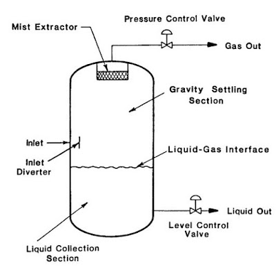
Figure 2 is a schematic of a vertical separator. In this configuration the inlet flow enters the vessel through the side. As in the horizontal separator, the inlet diverter does the initial gross separation. The liquid flows down to the liquid collection section of the vessel. Liquid continues to flow downward through this section to the liquid outlet. As the liquid reaches equilibrium, gas bubbles flow counter to the direction of the liquid flow and eventually migrate to the vapor space. The level controller and liquid dump valve operate the same as in a horizontal separator.
 |
| Figure 2 Vertical separator schematics. |
The gas flows over the inlet diverter and then vertically upward toward the gas outlet. In the gravity settling section the liquid drops fall vertically downward counter to the gas flow. Gas goes through the mist extractor section before it leaves the vessel. Pressure and level are maintained as in a horizontal separator.
Spherical Separators:
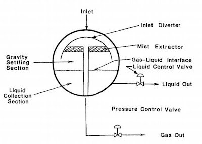
A typical spherical separator is shown in Figure 3. The same four sections can be found in this vessel. Spherical separators are a special case of a vertical separator where there is no cylindrical shell between the two heads. They may be very efficient from a pressure containment standpoint but because (1) they have limited liquid surge capability and (2) they exhibit fabrication difficulties, they are not usually used in oil field facilities. For this reason we will not be discussing spherical separators any further.
 |
| Figure 3 Spherical separator schematics. |
The above mentioned three types are the most commonly used two phase oil and gas separators in oil and gas production fields and industries, however there also exist some other types of separators as well which are employed for different applications or in different working conditions. They are as follows:
Cyclone Separators:
Cyclone separators are designed to operate by centrifugal force. These designs are best suited for fairly clean gas streams. The swirling action of the gas stream as it enters the scrubber separates the droplets and dust from the gas stream by centrifugal force. Although such designs can result in significantly smaller sizes, they are not commonly used in production operations because (1) their design is rather sensitive to flow rate and (2) they require greater pressure drop than the standard configurations previously described. Since separation efficiency decreases as velocity decreases, cyclone separators are not suitable for widely varying flow rates. These units are commonly used to recover glycol carryover downstream of a dehydration tower. In recent years, demand for using cyclone separators on floating facilities has increased because space and weight considerations are overriding on such facilities.
 |
| Figure 4 Cyclone separator. |
Two-Barrel Separators:
Two-barrel or double barrel separators are common where there is a very low liquid flow rate. In these designs the gas and liquid chambers are separated as shown in Figure 5. The flow stream enters the vessel in the upper barrel and strikes the inlet diverter. The free liquids fall to the lower barrel through a flow pipe. The gas flows through the gravity settling section and encounters a mist extractor en route to the gas outlet. The liquids drain through a flow pipe into the lower barrel. Small amounts of gas entrained in the liquid are liberated in the liquid collection barrel and flow up through the flow pipes. In this manner the liquid accumulation is separated from the gas stream so that there is no chance of high gas velocities re-entraining liquid as it flows over the interface. Because of their additional cost, and the absence of problems with single vessel separators, they are not widely used in oil field systems.
 |
| Figure 5 Double-barrel separator. |
Filter Separators:
Another
type of separator that is frequently used in some high gas/low-liquid flow
applications is a filter separator. These can be either horizontal or vertical
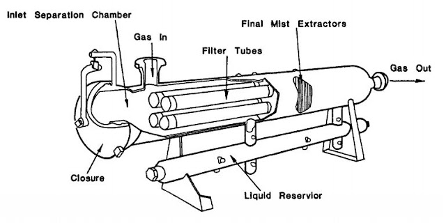
in configuration. Figure 6 shows a horizontal two-barrel design. Filter tubes
in the initial separation section cause coalescence of any liquid mist into
larger droplets as the gas passes through the tubes. A secondary section of
vanes or other mist extractor elements removes these coalesced droplets. This
vessel can remove 100% of all particles larger than about 2 microns and 99% of
those down to about 0.5 micron. Filter separators are commonly used on
compressor inlets in field compressor stations, final scrubbers upstream of
glycol contact towers, and instrument/fuel gas applications. The design of
filter separators is proprietary and dependent upon the type of filter element
employed.
 |
| Figure 6 Typical filter separator. |
In
applications where there is very little liquid flow, often a horizontal
separator will be designed with a liquid sump on the outlet end to provide the
required liquid retention time. This results in an overall smaller diameter for
the vessel.


It's very nice of you to share your knowledge through posts. I love to read stories about your experiences. They're very useful and interesting. Get more info about trunnion ball valve manufacturer in germany
ReplyDeleteThank you for the helpful blog, "Two-Phase Oil & Gas Separator Types." I want you to know that your information is invaluable for aspiring candidates. Keep sharing valuable updates!
ReplyDeleteChandu Biology Classes