Posts

Showing posts from 2018

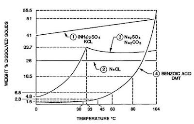
Design Calculation Of An Reverse Osmosis (RO) Module

Image
               Reverse osmosis is the most important technique of desalination of brackish (1000-5000 ppm salt) or sea water (about 35,000 ppm or 3.5% salt). Its potential was identified in the 1950s. But commercial exploitation was not possible until the 1960s. The development of high flux asymmetric cellulose acetate membrane by the phase inversion technique of Lobe and Sourirajan (1963) opened up commercial exploitation of this very important strategy of desalination. Currently, over 12,500 industrial scale desalination plants are operating worldwide with an average production rate of about 23 million cubic meter per day of potable water (less than 200 TDS). The largest sea water desalination plant is in Jeddah, Saudi Arabia, having a capacity of 56,800 cubic meter per day of potable water.     Problem Statement And Given Data: It is required to design an reverse osmosis (RO) module for production of 1500  m 3 /day potable water containing not more than 250 ppm salt fro

Two-Phase Oil & Gas Separator Types

Image
Produced wellhead fluids are complex mixtures of different compounds of hydrogen and carbon, all with different densities, vapor pressures, and other physical characteristics. The physical separation of these compounds is one of the basic operations in the production, processing, and treatment of oil and gas. To fulfill this separation two phase oil and gas separators are employed which mechanically separate from a hydrocarbon stream the liquid and gas components that exist at a specific temperature and pressure. Separators are designed in either horizontal, vertical, or spherical configurations. Horizontal Separator: Figure 1 is a schematic of a horizontal separator. The fluid enters the separator and hits an inlet diverter causing a sudden change in momentum. The initial gross separation of liquid and vapor occurs at the inlet diverter. The force of gravity causes the liquid droplets to fall out of the gas stream to the bottom of the vessel where it is collected. This liqu

Types Of Fouling In Heat Exchangers

Image
What is fouling in Heat Exchangers?              Fouling is the accumulation of unwanted material on the tube surfaces of the heat exchanger. After a period of operation the heat transfer surface of heat exchanger may become coated with various deposits presents in flow system. This coating represents an additional resistance to heat flow and thus decreased in performance. Fouling factors are best determined from experience with similar units in the same or similar service. When such information is not available, recourse may be had to publish data. The most comprehensive tabulation of fouling factors is the one developed by TEMA, which is available in Refs. [1, 2]. Fouling can occur by a number of mechanisms operating either alone or in combination. These include: Corrosion:           Corrosion products such as rust can gradually build up on tube walls, resulting in reduced heat transmission and eventual tube failure. This type of fouling can be minimized or eliminated b

Design Calculation (Sizing) Of A Crystallizer

Image
Problem Statement And Given Data: Given the following data and information, it is required to design a forced circulation crystallizer of the type shown in Figure 1 operating under vacuum. Figure 1 Forced circulation (FC) evaporation crystallizer.   Feed (an aqueous solution) rate, Qi = 15 m 3 /h, feed concentration, Ci = 200 kg/m 3 solution; feed temperature = 55 o C; average density of the solution = 1100 kg/m 3 and average specific heat = 0.90 kcal/kg. o C; operating pressure = 100 mm Hg (660 mm Hg vacuum); boiling point elevation of the saturated solution = 13 o C; saturation concentration at the crystallization temperature = 250 kg/m 3 ; magma density allowed, M T = 350 kg crystal/m 3 solution; crystal growth rate determined experimentally under the conditions of the crystallizer, G = 4.67 x 10 -8 m/s; crystal density = 1700 kg/m 3 ; desired dominant crystal size L D = 0.8 mm; heat of vaporization of water at the temperature of the crystallizer = 570 kcal/kg; su

Crystallizer Selection And Design

Image
Crystallizer Design Procedure:         The following steps are outlined for the design of a crystallizer of the Forced Circulation (FC) type. Although these calculations are limited to that style, the procedure has general application to other types of equipment. Choose the type of crystallizer that best meets the requirements for (a) product size, (b) product quality, (c) process economics, and (d) scale of operation. See Table 1 for a list of the general characteristics of crystallization equipment. Make a material balance, heat balance, and flow sheet.  Decide what retention time is required to make the required product, (a) by experience, and (b) from growth and nucleation rate data. Size the body on the basis of the controlling volume required for crystal retention with due consideration for the minimum cross-section required for vapor (evaporation) release. Size the heat-transfer surface (for evaporative types) and the recirculation rate.  Size

Crystallizer Selection And Design

Image
Guidelines For Crystallizer Selection: This is part one of a two-part feature that examines the fundamentals and discusses crystallization equipment selection and design. Part one focuses on the basics, providing guidance for crystallization equipment selection. Part two will focus on the crystallizer design procedure. The guidelines for crystallizer selection and operation in various chemical industry processes are discussed below. Information Required For Evaluation:         Before a potential crystallizer application can be properly evaluated, it is necessary to have certain basic information regarding the material to be crystallized and its mother liquor. Typical solubility curves are shown in Figure 1. Is the material a hydrated or anhydrous material? What is the solubility of the compound in water or any other solvents under consideration and how does this change with temperature and pH? Are there other compounds in the solution that coprecipitat