Posts

Cooling Tower Design Calculations - Height of Packing & Air Flow Rate

Image
Problem Statement & Given Data: Warm water at 45°C is to be cooled to 30°C by countercurrent contact with air in a tower packed with wood slats. The inlet air has a dry-bulb temperature of 31°C and a wet-bulb temperature of 22°C. The mass flow rate of water is 6000 kg/m 2 .h and that of air is 1.4 times the minimum. The individual gas-phase mass transfer coefficient is k Y’ a = 6000 kg/m 3 .h.∆Y’. The volumetric water-side heat transfer coefficient is given by h L a = 0.059 x L 0.51 x G S , in kcal/m 3 .h.K, where L and G S are mass low rates of water and air (dry basis). Determine (a) the dry air flow rate to be used, (b) the height of packing. Solution: (a)                                                Inlet air: T G = 31°C; T W = 22°C = T as                               Humidity (from Psychrometric chart), Y’ 1 = 0.01295.         Enthalpy, H’ = [2500 x Y’ 1 + (1.005 + 1.88 x Y’ 1 )] x (31 – 0) = 64.3 kg/kg dry air.                                 

Types of Petroleum Refinery - Complexity/Configuration

Image
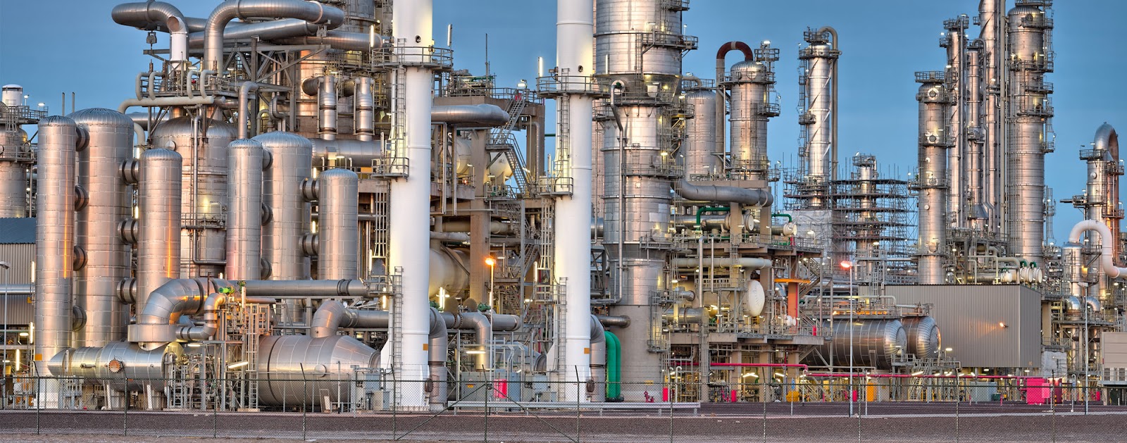
An oil refinery or petroleum refinery is an industrial process plant where crude oil is processed and refined into more useful products such as liquefied petroleum gas, gasoline or petrol, kerosene, jet fuel, diesel oil and fuel oils. Each petroleum refinery is uniquely configured to process a specific raw material into a desired slate of products. In order to determine which configuration is most economical, engineers and planners survey the local market for petroleum products and assess the available raw materials. Following are the petroleum refinery types/configurations used worldwide. Topping Refinery: The topping refinery just separated the crude into its constituent petroleum products by distillation, known as atmospheric distillation. Topping refinery produces naphtha but no gasoline. Schematic of Topping Refinery Hydroskimming Refinery: The hydroskimming refinery is equipped with atmospheric distillation, naphtha reforming and necessary treating proc

Common Cooling Tower Problems – Interference, Recirculation and Legioellosis

Image
Interference and Recirculation: A number of cooling towers may have to be used if the hot water load is large. The tower are very often installed at one place in the plant for convenience. Interference and recirculation are two common problems with cooling towers placed in proximity. Some of the moist air leaving a tower may be sucked into another tower installed “downwind” in the vicinity of the former [Figure 1(a)] affecting the performance. This is called “interference” . Sometimes a part of the moist air from a tower may be sucked into itself by the “forced-draft fan”. This is “recirculation” [Figure 1(b)]. The ratio of the “plume velocity” to the “wind velocity” is an important factor to determine the extent of recirculation. If this ratio is small, a forced-draft tower becomes more susceptible to recirculation [Figure 1(c)]. Both the phenomena of interference and recirculation reduce the enthalpy driving for cooling and adversely affect the performance of cooling towers.

Cooling Tower Description - Typical Values of Design Variables

Image
            A cooling tower is a special type of heat exchanger in which the warm water and the air are brought in direct contact for evaporative cooling. It must provide a very good contact of air and water in terms of the contact area and mass transfer coefficient of water vapor while keeping the air pressure drop low.  Figure 1 A single deck spray pond cooling system.            In the early years of industrial development, cooling of warm water for reuse was done in “spray ponds”. In a spray pond, as the name implies, a spray system located about six to eight feet above the water surface creates small droplets of warm water that cool down by evaporation in contact with air. This is simple and easy process but required a large pond area. It is inefficient (the effective heat transfer coefficient is about 3.5 Btu/h.ft 2 .°F or 20 W/m 2 .K), and creates the problem of entrainment and carryover of water droplets by air.                The first cooli

Sizing Of A Rotary Dryer

Image
        Rotary dryers , called the “workhorse of chemical dryers” , belong to the most widely used class of continuous dryers in process industries. These dryers are suitable for relatively free-flowing, non-sticky and granular materials; for example, almost all types of crystals after crystallization and washing. Typical applications of rotary dryers are in drying o table salt, sodium sulphate, ammonium sulphate, and many other salts, drying of sand, minerals, organic solids, polymer resin beads, to mention a few. A rotary dryer consists of a slowly rotating slightly inclined cylindrical shell fed with the moist solid at the upper end. The material flows along the rotating shell, gets dried and leaves the dryer at the lower end.          It is difficult, if not impossible, to design a rotary dryer on the basis of fundamental principles only. The available design correlations are a few in number and may not prove to be satisfactory for many systems. The design of a rotary

Design Calculation Of An Reverse Osmosis (RO) Module

Image
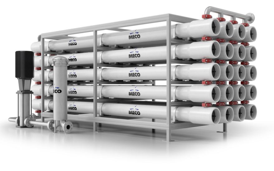
               Reverse osmosis is the most important technique of desalination of brackish (1000-5000 ppm salt) or sea water (about 35,000 ppm or 3.5% salt). Its potential was identified in the 1950s. But commercial exploitation was not possible until the 1960s. The development of high flux asymmetric cellulose acetate membrane by the phase inversion technique of Lobe and Sourirajan (1963) opened up commercial exploitation of this very important strategy of desalination. Currently, over 12,500 industrial scale desalination plants are operating worldwide with an average production rate of about 23 million cubic meter per day of potable water (less than 200 TDS). The largest sea water desalination plant is in Jeddah, Saudi Arabia, having a capacity of 56,800 cubic meter per day of potable water.     Problem Statement And Given Data: It is required to design an reverse osmosis (RO) module for production of 1500  m 3 /day potable water containing not more than 250 ppm salt fro